Thin Film System Introduction
Thin Film System Introduction
This chapter introduces the fundamentals of thin film optical systems used in OSC Low-E software, helping users understand various calculations and operations.
Film Stack Structure
The OSC Low-E film stack structure consists of five main parts. Light propagates from bottom to top, passing through each layer in sequence:
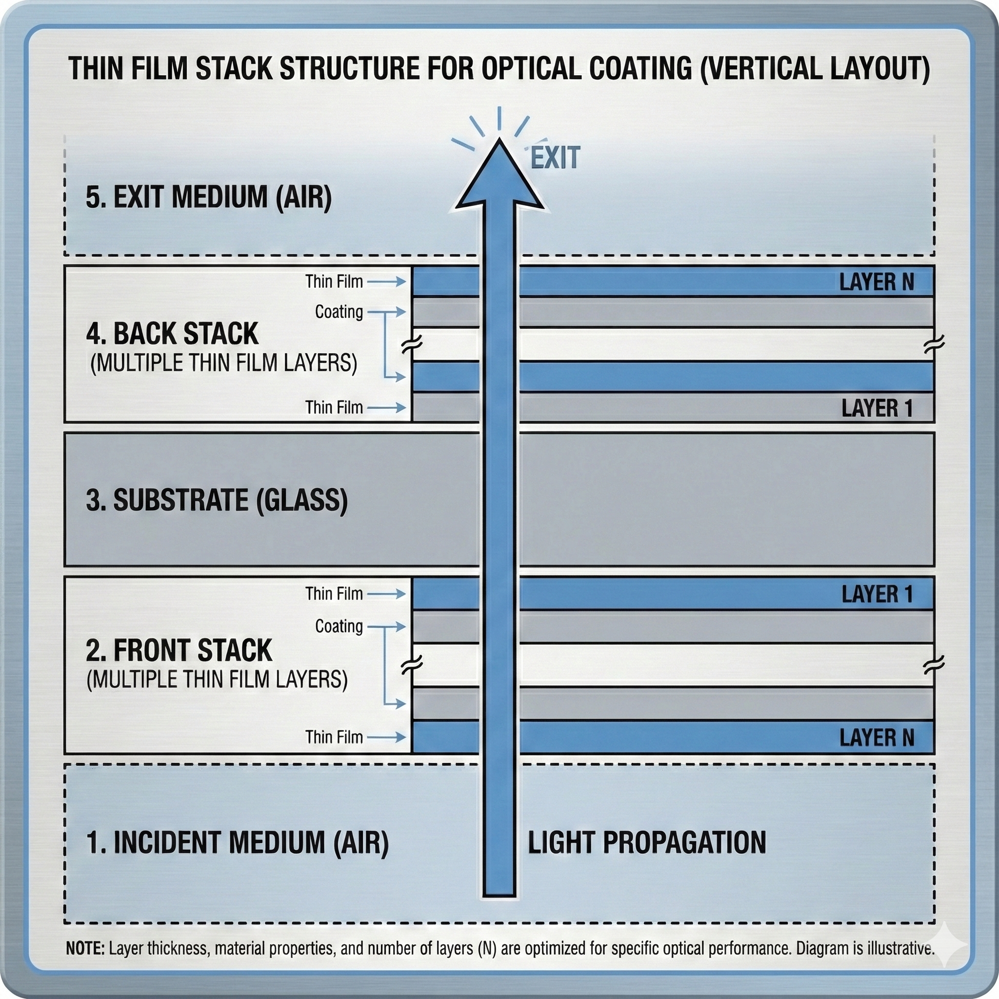
- Incident Medium: The medium where light enters, typically air
- Front Stack: Thin film layers coated on the front surface of the substrate
- Substrate: The glass base that supports the thin films
- Back Stack: Thin film layers coated on the back surface of the substrate
- Exit Medium: The medium where light exits, typically air
Layer Numbering Convention
OSC Low-E strictly follows these physical definitions, regardless of the light incidence direction:
- Layer 1: Always the layer closest to the Substrate
- Layer N: Always the layer farthest from the Substrate (closest to incident/exit medium)
Front Stack and Back Stack Definitions:
- Front Stack: Located on the front surface of the substrate. Layer 1 is adjacent to the substrate, Layer N is adjacent to the incident medium
- Back Stack: Located on the back surface of the substrate. Layer 1 is adjacent to the substrate, Layer N is adjacent to the exit medium
Spectrum Calculation Types
OSC Low-E supports 12 basic spectrum calculation types, divided into three categories:
A. Front Stack Design
Considers only Incident Medium + Front Stack + Substrate.
| Type | Name | Description |
|---|---|---|
| Forward Reflectance | FrontDesignRfront | Light enters from incident medium, measures reflectance R |
| Forward Transmittance | FrontDesignTfront | Light enters from incident medium, measures transmittance T |
| Backward Reflectance | FrontDesignRback | Light enters from substrate, measures reflectance R' |
| Backward Transmittance | FrontDesignTback | Light enters from substrate, measures transmittance T' |


B. Back Stack Design
Considers only Substrate + Back Stack + Exit Medium.
| Type | Name | Description |
|---|---|---|
| Forward Reflectance | BackDesignRfront | Light enters from substrate, measures reflectance R |
| Forward Transmittance | BackDesignTfront | Light enters from substrate, measures transmittance T |
| Backward Reflectance | BackDesignRback | Light enters from exit medium, measures reflectance R' |
| Backward Transmittance | BackDesignTback | Light enters from exit medium, measures transmittance T' |


C. Whole Stack Design
Considers the complete system: Incident Medium + Front Stack + Substrate + Back Stack + Exit Medium.
| Type | Name | Description |
|---|---|---|
| Forward Reflectance | WholeStackRfront | Light enters from incident medium, measures total reflectance R |
| Forward Transmittance | WholeStackTfront | Light enters from incident medium, measures total transmittance T |
| Backward Reflectance | WholeStackRback | Light enters from exit medium, measures total reflectance R' |
| Backward Transmittance | WholeStackTback | Light enters from exit medium, measures total transmittance T' |


Whole stack calculations treat the "substrate thickness" as a finite thickness layer, thus including incoherent effects (interference effects are averaged out) of the substrate.
Related Terms
For more terminology, please refer to the Glossary.